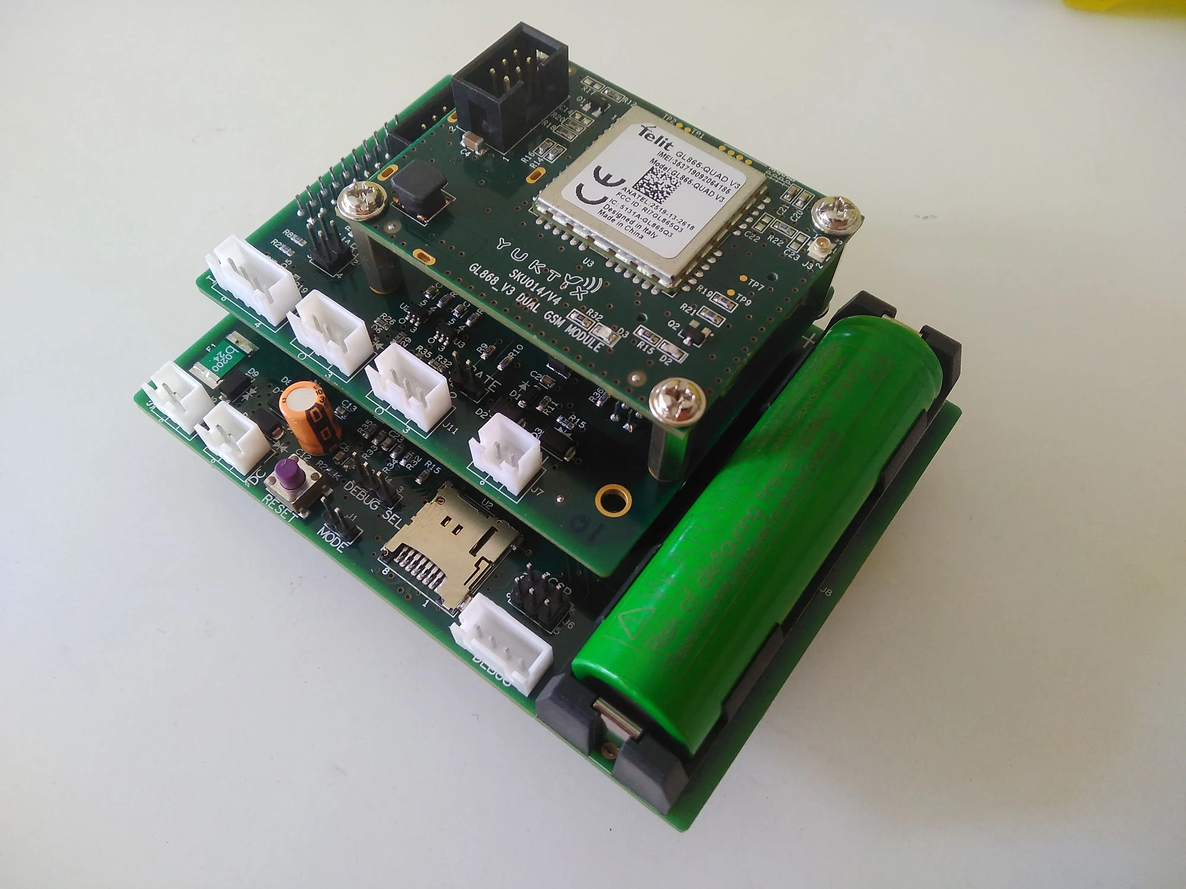
Yuktix Greensence PCB is part of Yuktix ankiDB(™) micro stack. This is a small form factor PCB that can run from solar or DC power. It provides single cell solar charger, and is ideal to run your applications in remote locations from a 6V solar panel. The PCB consumes very little current, allowing you to do sensors data gathering without a power socket. This PCB provides I2C, SPI, GPIO and ADC for sensor cards. The PCB comes with ankiDB(™) micro OS that is optimized for low power data collection and transmission. This PCB provides multiple networking options by using Yuktix modular networking cards.
Main Features
- ankiDB micro OS
- Extreme low power applications
- GPRS and Sub Giga Hz networking
- Easy Configuration with SCP tool
- Bootloader for easy programming
- Single cell solar charger
- Run from 6V Solar
- Run from 12V/24V DC
- SD card for local storage
- Interface multiple sensors
- 2 UART
- 6 ADC
- I2C bus
- SPI bus
- 10 GPIO
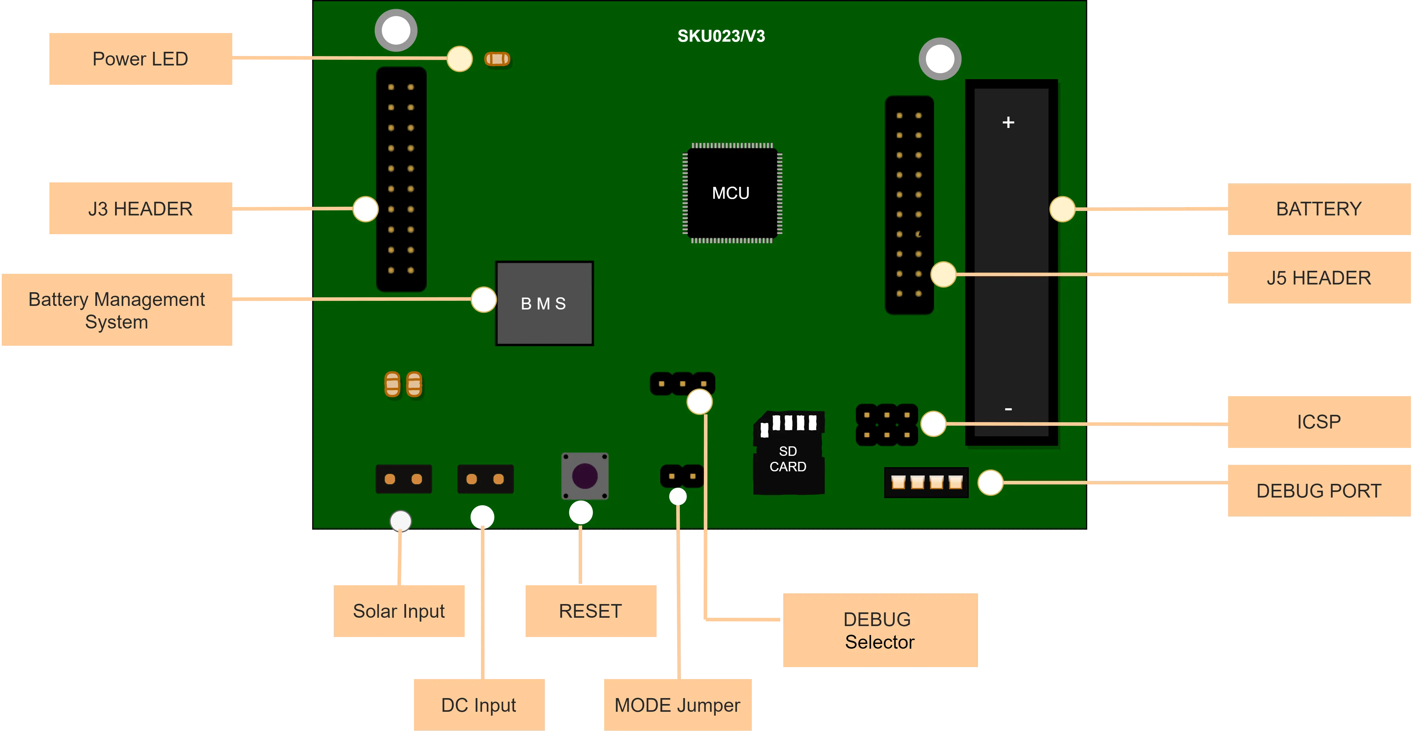
| Solar Charger | The GreenSense PCB includes a single cell solar charger (based on LTC1732) that can be used with 18650 size lithium ion cells. The charger can provide upto 1A of charging current. The sense resistors are provided to control the charging rate based on cell capacity. There are also MOSFET based cut off switch to ensure that battery is not deep discharged if we are not providing charging for a long time. The PCB can be used with a 6V solar panel. | |
| Microcontroller | The ATMEGA1284P is a low-power CMOS 8-bit microcontroller based on the AVR enhanced RISC architecture. The chip has 128 KB of Flash, 16 KB of RAM and 4KB of EEPROM and can run upto 20 MHz. The main factors behind the choice of microcontroller were low power consumption (pico power) and AVR architecture for running ankiDB micro OS. The Yuktix GreenSense PCB provides 8MHz and 7.3728 MHz oscillators for the CPU. | |
| DC Power | The GreenSense PCB can also be run from a DC power source. We can run the PCB from a 12V or 24V power supply. | |
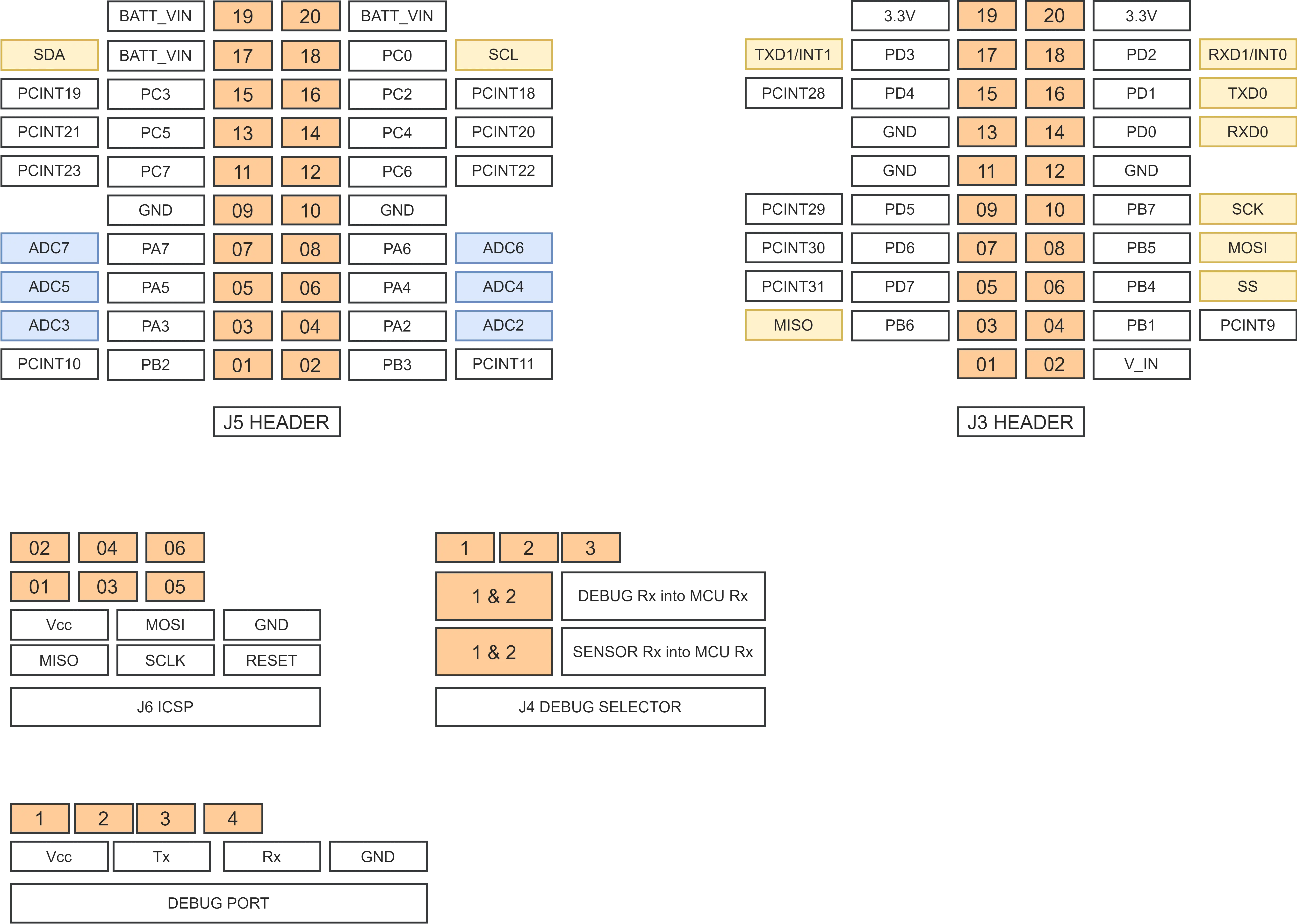
| Sensors interface | The GreenSense PCB provides I2C, SPI, GPIO, and UART pins for sensor interfacing. Please see the J3 and J5 sensor header details above. |
Low power discharge
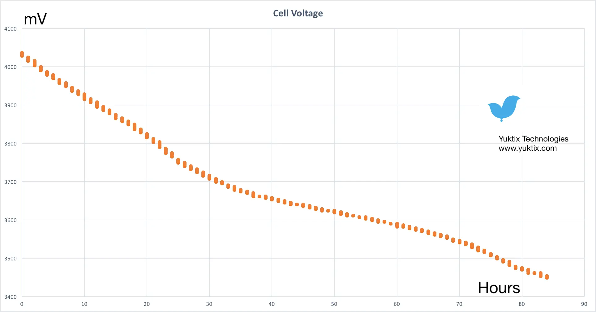
GreenSense PCB is low power PCB that can operate on a single cell for days. Here we show the discharge curve of the Li-ion cell when the power sources are removed. For this experiment, a charged 2600 mAh cell was used that lasted for about 90 hours. (~ approx. 4 days) During the experiment, the PCB was active and sending data to server every 5 minutes. A 3500mAh cell should provide even longer life.
With a small 6 Watt 6V solar panel, the units can run in remote locations day in and day out. The GreenSense PCB have been tested in locations with multiple overcast days during monsoon season as well.
Direct to cloud
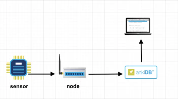
GreenSense PCB can send data directly to an ankiDB server running on the Internet without a router. The node interfaces with sensors on one side and provides direct connectivity the Internet using 4G or low orbit satellite modems.
Local networking
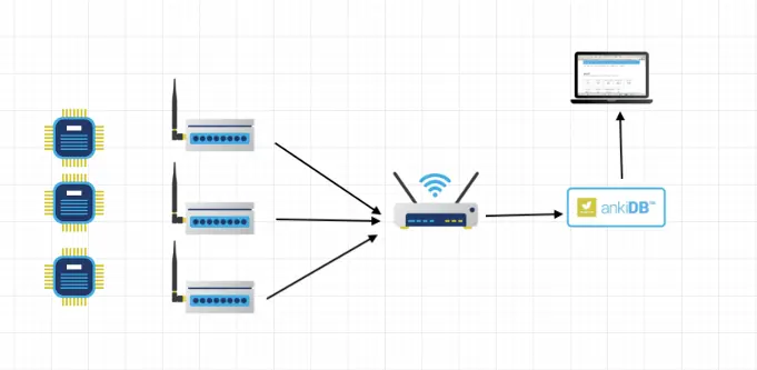
This setup is a local wireless network of GreenSense nodes running ankiDB micro OS interfacing to a solar router . The solar router collect the data from multiple nodes. The router then sends data to a server running on the Internet using 4G or low orbit satellites.
Firmware Upload
There are two ways to update the firmware on Yuktix GreenSense PCB. The GreenSense PCB ships with an STK500 compatible bootloader. You can also compile the stk500 bootloader available in the Arduino github repository for ATMEGA1284P. You only need to change few flags in the makefile. The required FUSE settings and Makefile changes are documented on the fuse and bootloader page
T You will need an in-system programmer like AVRDUDE on your PC to interact with the bootloader and upload your compiled hex file on the serial line. We recommend using FTDI TTL-232RG cable to make a serial connection betweeen your PC and the GreenSense board using the DEBUG PORT of the PCB. The connection diagram for FTDI TTL-232RG cable to GreenSense board is shown below.
| Red | |
Vcc | NC | Do not connect |
| Yellow | |
Rx | 2 | MCU Tx |
| Orange | |
Tx | 3 | MCU Rx |
| Black | |
GND | 4 |
Debugging and configuration
The GreenSense PCB debug port can be used to view messages from the PCB. To connect a serial cable to debug port, use the details of the port shown in the PCB pinout diagram. The default communication is set for baud 38400 and 8N1. To change the configuration, you can use the Yuktix serial command processor tool (SCP).