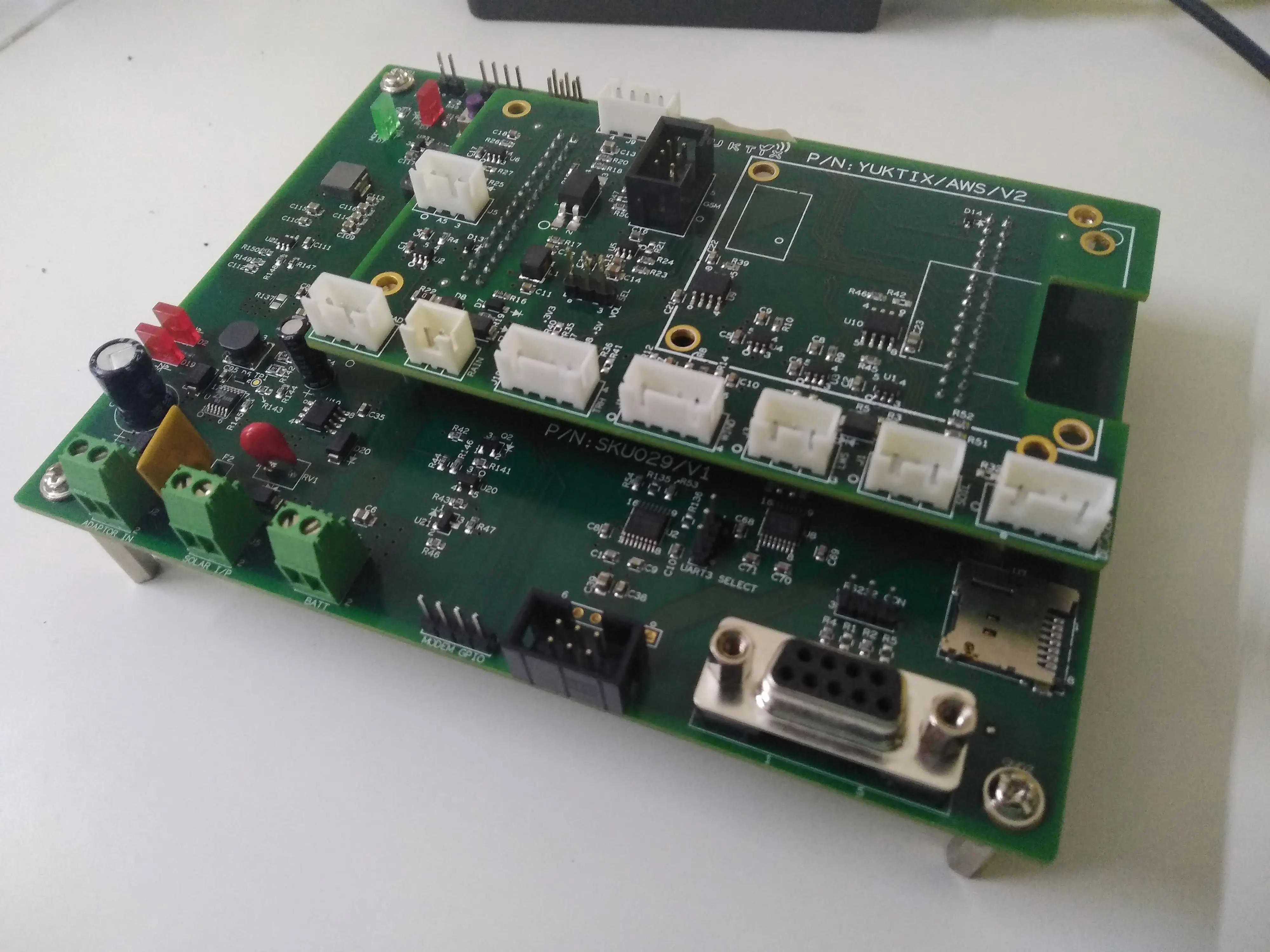
Solar router PCB is a part of Yuktix ankiDB(™) micro hardware which can act as a gateway to collect data from sensors and transmit it over wireless networks. Product from this PCB can be used as a aws station as well as router to collect data from multiple greensense nodes and transmit it to the cloud via GSM (4G or 2G) like connectivity. This PCB MCU supports Yuktix ankiDB(™) micro OS in which there are libraries for 2G, 4G and XBEE modems and a wide range of sensor libraries. This PCB provides I2C, SPI, GPIO and ADC for sensor cards and provides us various communication modes like RS232, TTL etc.
Main Features
- ankiDB micro OS
- 2A Solar charger
- Router and AWS applications
- GPRS and Sub GigaHz networking
- Easy Configuration with SCP tool
- Bootloader for easy programming
- Run from 12V Solar
- Run from 24V DC
- On board RTC
- SD card for local storage
- Interface multiple sensors
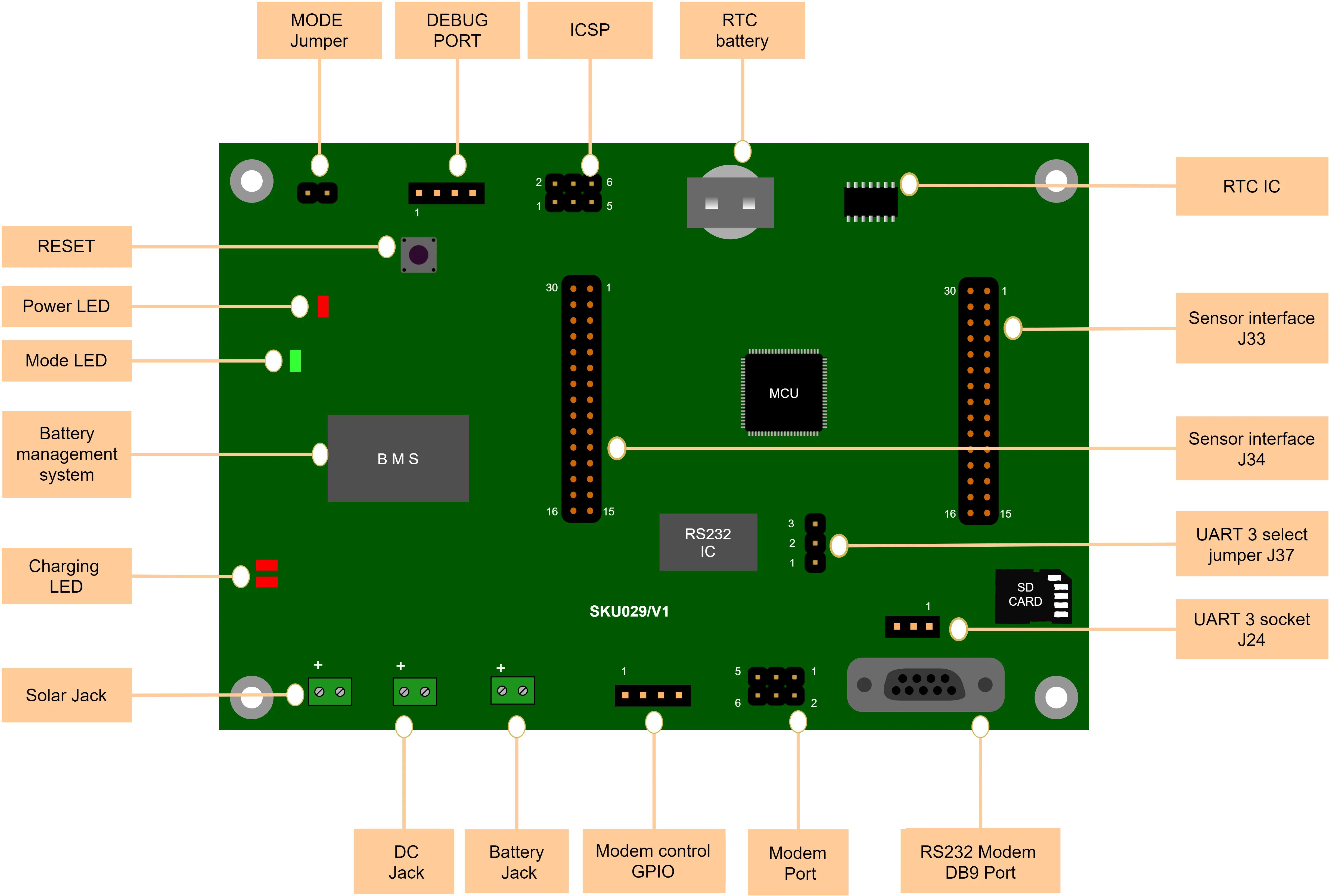
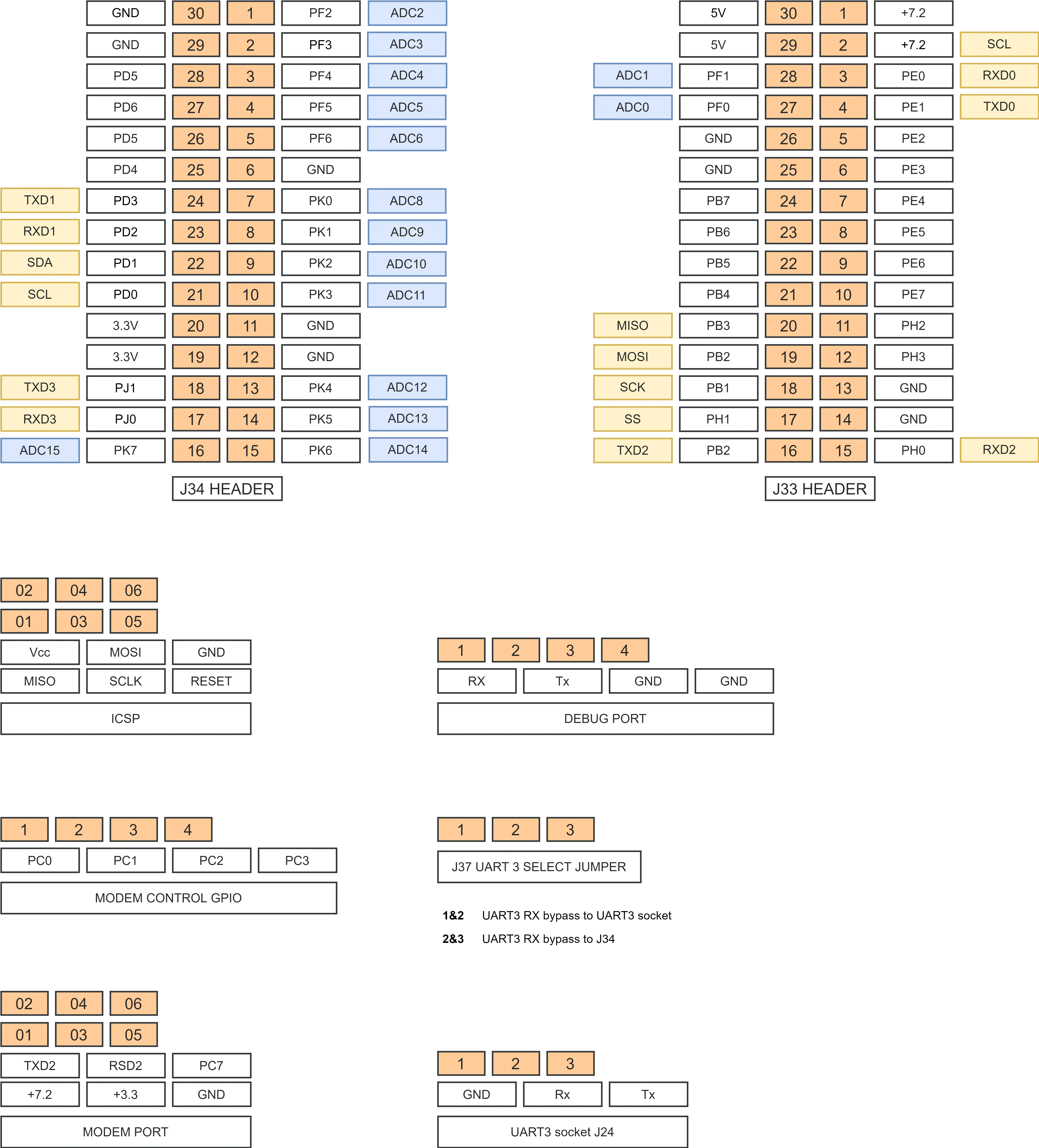
- 4 UART
- 14 ADC
- I2C bus
- SPI bus
- 38 GPIO
| Solar Charger | Solar router PCB has a robust power management system that supports rapid solar charging it can charge battery with upto 2A of charging current. It also supports smart power cut options like when the battery is low it cuts power to prevent the battery from going into deep discharge as it also increases battery life time. | |
| Microcontroller | The ATMEGA 640 is a low-power CMOS 8-bit microcontroller based on the AVR enhanced RISC architecture. By executing powerful instructions in a single clock cycle, the ATmega640 achieves throughputs approaching 1 MIPS per MHz allowing the system designer to optimize power consumption versus processing speed. The main factors behind the choice of microcontroller were low power consumption (pico power) and AVR architecture for running ankiDB micro OS. | |
| DC Power | DC powering option is useful when there is no solar light available. So the user can power this PCB by 24V DC. | |
| Sensors interface | The solar router PCB provides I2C, SPI, GPIO, and UART (TTL/RS232) pins for sensor interfacing. Please see the J33 and J34 sensor header details above. |
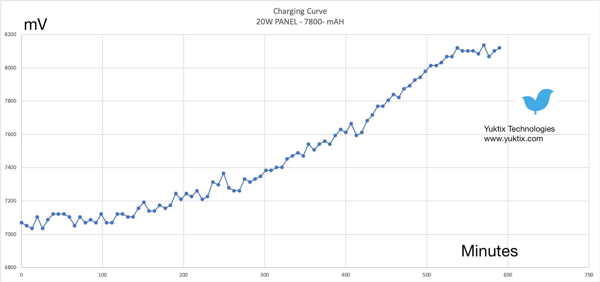
Battery charging curve
The graph shown above is charging characteristics of 7800 mAH discharged battery with time with 20W solar panel which can give upto 1A of current. Yuktix solar router PCB's battery management system can charge 7800 mAH battery in approximately 600 minutes.
Battery discharge curve
The graph shown above is discharge characteristics of 7800 mAH battery with time. Yuktix solar router can withstand upto 150 hours on battery without solar charging.
Solar router for networking
This setup is done to create a local wireless network of greensense nodes running ankiDB micro OS and solar routers (solar router card). The routers collect the data from the nodes. The routers then send data to a server running on the Internet using 4G or low orbit satellites.
Direct to cloud node
The solar router aws station can send data directly to an ankiDB server running on the Internet. The PCB interfaces with sensors on one side and provides direct connectivity the Internet using 4G or low orbit satellite.
Firmware Upload
There are two ways to update the firmware on Yuktix solar stick PCB. The Solar router PCB ships with an STK500 compatible bootloader. You can also compile the stk500 bootloader available in the Arduino github repository for ATMEGA640. You only need to change few flags in the makefile. The required FUSE settings and Makefile changes are documented on fuse and bootloader
You will need an in-system programmer like AVRDUDE on your PC to interact with the bootloader and upload your compiled hex file. We recommend using FTDI TTL-232RG cable to make a serial connection betweeen your PC and the solar router board. The connection diagram for FTDI TTL-232RG cable to solar stick board is shown below.
| Red | |
Vcc | NC | Do not connect |
| Orange | |
Tx | 1 | MCU Rx |
| Yellow | |
Rx | 2 | MCU Tx |
| Black | |
GND | 3,4 |
Debugging and configuration
The solar router PCB debug port can be used to view messages from the PCB. To connect a serial cable to debug port, use the details of the port shown in the PCB pinout diagram. The default communication is set for baud 38400 and 8N1. To change the configuration, you can use the Yuktix serial command processor tool (SCP).